Wednesday, November 27, 2013

Sparkfun, legos and screws

The items I ordered from Sparkfun have arrived. If you are around today, you can stop by my office to pick them up. I will definitely be in my office between 2:00-2:30 PM.

The Lego parts have not yet arrived, so they will be available next week.

Screws can also be picked up next week.

If you are going to be mating acrylic parts together to make a movable joint, I have ordered a supply of binding posts. These may work better than Lego axles for some applications. You can look at the specifications of these items at McMaster-Carr - the part numbers ar in the image below.

Inline image 1

3D Printing and Laser Cuting

I have begun the process of part fabrication for those teams that have submitted part requests.

For the time being, I will place the finished parts in a box on the table at the back or Perry 311.

PLEASE DO NOT TAKE ANY PARTS THAT ARE NOT YOURS!!!

Also please communicate with your team members if you pick-up the parts.

It is going to take a lot of time and effort to get all the parts printed/cut, and I do not want to have to make additional work because parts have "disappeared".

I will be able to print 3D parts over the Thanksgiving break, so if your team has your part designs ready, please submit them ASAP.  It takes substantial amount of time to print the parts, so I would like to be able to have parts to print so that I don't end up with a big backlog during the final week.

As an example, the parts in the image below took 15 hours to print...

A 15 hour print job!!!

Monday, November 25, 2013

Design Project - Slight Change...

A number of groups have been running into problems incorporatin the LCD screen into their project because they are running out of I/O pins.

Therefore - you only have to use the LCD screen in your project if you need/want to have the ability to show test/graphics.

Sunday, November 24, 2013

This week...

Lectures 

There will not be a lecture this week. I will, however, be posting a number of SolidWorks videos where I go through the steps to create a number of parts similar to those you have worked both as homework and as quizzes.

In preparation for the final exam next week please review all your SolidWorks quizzes. I might also suggest that you review some of the SolidProfessor videos.

Labs

Labs this week should be used by the design groups to meet and finalize your designs in preparation for part fabrication next week. Repeating from the Final Version of the Design Project Specifications...
  • The part files for the parts that your team are requesting to be fabricated must be submitted by 5 PM on Nov 27th. The submission should also include a request for the required number of Lego connectors and servo motor screws.

The TA's will be available in the labs during the regularly scheduled labs on both Monday and Tuesday. You should stop by and meet with them if you have questions regarding any of your grades or if you have Lab Challenges that you wish to have graded.


SolidWorks Lab Challenges

  • If you are submitting "late" SolidWorks challenges, the maximum grade will be 80% of the original point value.
  • If you are submitting "corrected" SolidWorks challenges, the maximum grade will be 90% of the original point value.

Arduino Challenges

  • If you are submitting "late" Arduino challenges, the maximum grade will be 90% of the original point value.

Blog Posts

You design blogs will be reviewed during the upcoming week. You should make sure that your team has made all the required entries. You should also recall that if your team ONLY has the required entries, your grade for this portion of the project will reflect that there was minimal effort expended. 


Thursday, November 21, 2013

Design Project - Part Fabrication

Part Fabrication

I would like to begin the process of 3D printing and laser cutting parts next week. If your design team has progressed to the point where you would like to have parts fabricated please do the following:

3D printed Parts

  1. Review the video that shows how to use the CatalystEX software (see below).
  2. Use the CatalystEX software that is available on the two podium computers in Perry 311 and Perry 321 to verify the total material usage for your 3D printed parts. You material usage should be less than 4.0 cubic inches. It is okay if the total is slightly over. If your required material volume is way over the 4 cubic inch limit you need to meet with me as a team to discuss your options.
  3. Send an email with the parts that you want printed. The parts should be in SolidWorks *.SLDPRT format, The final conversion to STL files will be done by the TA's prior to printing.
               EMAIL: daniel_sullivan@uml.edu
               SUBJECT: 22.201 3D Part Print Request
Video


Laser Cut Parts

  1. The pictures below are of a model that will produce a "good" laser cut part.
  2. Send an email with the parts that you want printed. The parts should be in SolidWorks *.SLDPRT format, The final conversion to the format required by the laser cutter (DXF) will be done by the TA's prior to printing.
          EMAIL: daniel_sullivan@uml.edu
          SUBJECT: 
    22.201 2D Part Laser Cut Request

Parts that you design to be laser cut should have an obvious 2D geometry. The parts should be extruded to the desired part thickness of either 0.125" or 0.25".

Each part should have an identifying set of letters on the interior of the part. Unless otherwise specified, the letters will be etched into the surface of the part. For example, the part shown below will have four holes and the words Arduino UNO etched into the surface.


Design Project Parts Ordered...

These items were ordered today. Hopefully they will arrive by next Wednesday, but they will definitely be available on Monday Dec. 2nd.  I ordered a few extra H-Bridges, let me know if your team would like to use one. I have ordered #6 self tapping screws (lengths 5/8", 3/4" 1") that you should be able to use to attached items to the 3-D printed parts.


Tuesday, November 19, 2013

UPDATE --- Quiz 3 Retest - Monday Nov 25th

The following are the instructions for taking the quiz.

Instructions:
  1. In order to take the quiz you need access to an internet connected computer that has SolidWorks 2013 installed. 
  2. You will be taken this quiz outside of the normal lab hours.
  3. You are responsible for following the detailed instructions included with the quiz sheet.
  4. The quiz duration is 35 minutes and will be give at two times 6:00 PM and 9:00 PM.
  5. If you plan on taking the quiz using a UML ME Lab computer, then you should make sure that you arrive early to the lab so that you are seated and logged on by the time the quiz begins.
  6. At the designated quiz time (6PM) or (9PM) you should click the link below to access the quiz directory on the course Google drive.
  7. You should then open the folder that corresponds to the last digit of your Student ID and download the PDF it contains.
  8. You should follow the quiz instructions EXACTLY. There may be dimensions that you need to modify - these modifications will be based on your Student ID. You must also use the designated naming convention.
  9. At no later than 6:36 PM or 9:35 PM, you should have submitted your completed quiz. The quiz submission will be in the form of a SolidWorks Part and you will submit the part via email to 22201sullivan@gmail.com.

If you wish to practice for the Quiz, the Quiz 3 Re-test folder contains
copies of the original quizzes and my solutions

Grade update, an offer to make back some points, the Final Exam and t-shirts...

Pre-Lab Grades (5%)

As I have mentioned a couple of times, since SolidProfessor did not provide a good interface for allowing students to verify that they had completed each pre-lab, I have decided to not deduct any points from this 5% component of the final course grade. I am just working under the assumption that you have all done this work and thus have earned the 5%.


Quiz Grades (20%)

I have posted a locked Excel sheet that contains the grades for Quizzes 1 through 5. I have asked the TA's to get the grades inputted for quizzes 6 and 7 as soon as possible. I am also working on getting the grades together for those of you who took the Retakes for Quizzes 1 and 2. I will try to repost an updated quiz grade sheet this weekend.

******   Click here to access the Excel sheet. ******

As listed on the course syllabus, the quizzes account for 15% of the course grade. The Excel sheet contains a column that reports an overall quiz grade out of 15 points. Instead of reporting an average of all the grades, I sorted the grades and divided them into 4 groups (quartiles). The averages of each of these are as follows:
Q(1) - 18.8 ..... 94%
Q(2) - 16.0 .... 80%
Q(3) - 13.6 .... 68%
Q(4) - 8.9 .... 45%


SolidWorks Projects (15%)

I have placed a folder on the google drive that contains all the SolidWorks Projects that you should have completed. I preparation for the Final Exam, you should make sure that you have completed all these assignments.

******   Click here to access the Folder  ******  

I will be posting the grades that have been recorded for these projects over the weekend. I would like to give all students the opportunity to get credit for this material so if you...

  • did not complete the assignment
  • did not get full credit for the assignment
  • did the assignment but feel that the grade was entered incorrectly
You have two opportunities to have the TA's review your work and give you credit for the assignment:
  • Next week during regularly scheduled labs on Mon, Tue and Wed
  • The week of Dec 9th during the regularly scheduled labs on Mon, Tue and Wed.

Arduino Projects (15%)

I have placed a folder on the google drive that contains the three Arduino Projects that you should have completed.

******   Click here to access the Folder  ******  

I would also like to give all students the opportunity to get credit for this material. Since you are already working in groups for your design project, you may work in groups to get these three assignments completed.

When you have the projects completed, you should present them to one of the TA's who will then check the project and then assign credit. You should present with each assignment a printed copy of the code that contains the names of your group members and the assignment number as a comment line at the top of the sketch.

You have two opportunities to have the TA's review your work and give you credit for the assignment:
  • Next week during regularly scheduled labs on Mon, Tue and Wed
  • The week of Dec 9th during the regularly scheduled labs on Mon, Tue and Wed.


Final Exam (25%)

The final exam will take place in each lab session during the week of December 2nd. The final exam will only cover SolidWorks material and you will be required to both make parts from drawings and to modify part files that you will download from the Google Drive.

Some of the problems will require you to adjust part dimensions based upon a code number on your exam sheets and you will be required to write down part volumes for some of the parts that you create.

You will need to submit the parts that you create as a single zipped folder. Please make sure that you are familiar with the process before sitting down for the exam.

In order to make sure that there are enough PC's for every student, please attend your scheduled lab session for the final exam.

I have uploaded to the Google Drive a collection of part drawings that you can use to test yourself. 


SolidWorks T-shirts (Free)


 I received 100 t-shirts from SolidWorks that I would like to distribute to the class. I have about 25 each of the sizes S, M, L, and XL.

I have create a Doodle Poll where you can request a shirt and specify the size. This is a "first-come, first serve" operation. The shirts will be given distributed to those "lucky" individuals during the final exam.

******  Link to the Doodle Poll  ******  


Lego Connector Sample Part

For those design teams that are planning on using either Lego pins or Lego Axles, I have created a SolidWorks model that you can use to obtain the required dimensions. This part has been 3D printed and the pin connectors fit nicely and allow for easy rotation.

SolidWorks File


Actual 3D printed part with pins inserted...


Using an IR remote to Control an Arduino Project

For some projects it is desirable to be able to control the system remotely. One easy way to do this is via an IR remote control.

In order to accomplish this you need to obtain an IR receiver module. These are rather inexpensive components and can be purchased or scavenged from old VCRs. DVD's and other remote control devices. If you wish to purchase you can do so from Sparkfun or Adafruit.

The Adafruit site has a nice tutorial on setting up and using the receiver.

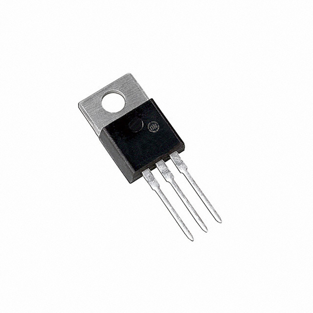
The IR receiver module that I am using is shown below. The diagram notes both the model number and the pin connections. Note that all IR receiver modules will have the same three connections, but the order of the connections may be slightly different. You can see this if you compare the one below with the similar diagram on the Adafruit site.

For the connections to the Arduino: Vcc goes to +5 V, Vout goes to a digital input Pin.


For the examples that I will be using, the IR Receiver is connected to P11 and three LED's are connected to digital pins P2, P3, and P4. The final configuration is shown here:


Download and Install IR Remote Library

The library that I recommend was written by Ken Shirriff. He has a full description of the project on his blog under the post A Multi-Protocol Infrared Remote Library for the Arduino.

Step 1: Download the library from GitHub and install the library using the following directions:


Step 2: Test system

As an initial test of your system your should upload and run one of the example sketches that comes with the IR Remote Library. File -> Examples ->  IRremote -> IRrecvDemo. Running this sketch will allow you to both verify that you have correctly configured your IR Receiver module and obtain the IR codes from whatever IR Remote control that you wish to use.

After loading and uploading the sketch, open the Serial Monitor and then push a button on your remote control. If the system is working, you should see something similar to this...


You should notice that every time you push a button, you will see a different sequence of letters and numbers. If you hold down the key you will see a repeat code of FFFFFFFF. The library is decoding the IR signal and outputting a value in Hexadecimal format. If you want to check out how Hexadecimal (base 16) compares to both decimal (base 10) and binary (base 2) you can look at this online converter.

The Arduino code will recognize a hexadecimal value as a regular integer, however for these values you need to use the variable identifier long instead of int because these 8 digit hexadecimal numbers are larger than the upper limit of the int range. In decimal format FFFFFFFF is 4,294,967,295.

If all is working correctly, you can go ahead and note down the codes for the remote control keys that you want to use. For the case of my remote control, I wanted to use the first four digits on the number pad and the codes for these for keys are as follows:

button 1 - FF728D
button 2 - FF52AD
button3 - FF929D
button4 - FFB24D

In order to use these as hexadecimal numbers in the Arduino code, it is necessary to prepend an identifier so that the code does not mistake these values as a string or some other variable name.  The identifier is 0x so the variables that we will use in the sketch become:

button 1 - 0xFF728D
button 2 - 0xFF52AD
button3 - 0xFF929D
button4 - 0xFFB24D

Step 3: Understand the particular lines that are required to make IRremote function.

Before presenting the entire sketch it may be helpful to look at the specific lines of code that relate to the IRremote library (some of my comments have been take from this page)

#include <IRremote.h>    This line is place at the beginning of the sketch and alerts the Arduino IDE that it should include the IRremote library when the sketch is compiled.

int RECV_PIN = 11;    This sets a variable name for the digital pin that is connected to the Vout pin of the IR receiver module. The example code uses P11, but any digital I/O pin can be used.

long button1 = 0xFF728D;    This is one of the variable declarations that provides a variable name to the hexadecimal number that corresponds to the buttons on the remote. Note that the variable identifier long has been used instead of int.

IRrecv irrecv(RECV_PIN);     IRrecv is a function that is defined by the IRremote library. This creates a IRrecv object that is called irrecv and this object is connected to RECV_PIN which has been defined as P11. Note that irrecv is a user defined name and you could use "bob" or another descriptive name. The use here is analogous to creating a Servo object when using the Servo library.

decode_results results;   This line creates a memory location that is used to store the information
received from the decode function of IRremote

irrecv.enableIRIn()
Begin the receiving process. This will enable the timer interrupt which consumes a small amount of CPU every 50 µs.
irrecv.blink13(true)
Enable blinking the LED when during reception. Because you can't see infrared light, blinking the LED can be useful while troubleshooting, or just to give visual feedback.
irrecv.decode(&results)
Attempt to receive a IR code. Returns true if a code was received, or false if nothing received yet. When a code is received, information is stored into "results".
results.decode_type: Will be one of the following: NECSONYRC5RC6, or UNKNOWN.
results.value: The actual IR code (0 if type is UNKNOWN)
results.bits: The number of bits used by this code
results.rawbuf: An array of IR pulse times
results.rawlen: The number of items stored in the array

if (results.value == button1){digitalWrite(ledBlue, HIGH);}    This if statement compares the value that has been stored in results to the first of the four button codes

irrecv.resume()
After receiving, this must be called to reset the receiver and prepare it to receive another code.

Step 4: Create sketch to respond to specific IR signals from remote

The video and code show a simple application of the IRemote library. Four buttons are defined and buttons 1, 2, and 3 each turn on one LED. button 4 then turns all the LED's off.

(Video)


(sketch)

Monday, November 18, 2013

The team blogs


  1. http://hovercraftmen.blogspot.com/
  2. http://nick-sylvia-josh-morris.blogspot.com/
  3. http://22201rubberbandgunner.blogspot.com/
  4. http://medesproject.blogspot.com/  
  5. www.22201-masterhand.blogspot.com
  6. http://arduinocreation.blogspot.com/
  7. http://22201tank.blogspot.com/
  8. http://chrispetereddie.blogspot.com/
  9. http://teamredemptiondesignproject.blogspot.com/
  10. http://matertherepotruck.blogspot.com/
  11. http://arduino-project-dancing-tree.blogspot.com/
  12. http://rghg808.blogspot.com
  13. http://22-201fall2013project.blogspot.com/
  14. http://designlabproject.blogspot.com/
  15. http://mechanicallab.blogspot.com/2013/11/the-teams-name-is-ardunio801-which.html
  16. http://22201mrroboto.blogspot.com/
  17. http://hilton22201designproject.blogspot.com
  18. peanutbuttahchocolateflava.blogspot.com
  19. 22FinalDesignation201.blogspot.com
  20. http://22201project.blogspot.com
  21. http://roy-melanson-project.blogspot.com
  22. http://projectloh.blogspot.com/
  23. http://22201-dsaw.blogspot.com/2013/11/choosing-project.html
  24. http://www.tiltmaze.blogspot.com/
  25. http://pimpininoakland.blogspot.com
  26. http://teambryan22201.blogspot.com
  27. http://bbteam2013.blogspot.com
  28. http://806mechanicaldesign.blogspot.com/
  29. http://22201-thedreamteam.blogspot.com/
  30. 22-201-deathbydonkeypong.blogspot.com
  31. http://team-2-fast.blogspot.com/
  32. http://codebreakersengineering.blogspot.com/
  33. http://22201hmp.blogspot.com/
  34. http://lightseeker2000.blogspot.com/
  35. http://team-infrared.blogspot.com/
  36. http://arduinobubblesproject.blogspot.com/
  37. http://mzeromin.blogspot.com/
  38. http://teamteamname.blogspot.com/
  39. http://teamcatapult.blogspot.com/
  40. http://arduinoboat.blogspot.com/
  41. http://arduinoproject1.blogspot.com/
  42. http://boostedlife1055.blogspot.com
  43. http://22201nunchuklaserbot.blogspot.com/
  44. http://rectanglebear.blogspot.com/
  45. http://tjjmplowkings-22-201.blogspot.com/
  46. http://umldesignlab.blogspot.com/
  47. http://umldesignlab.blogspot.com/
  48. http://22201klannspiderbot.blogspot.com/
  49. http://rccarprototype.blogspot.com/

Saturday, November 16, 2013

An example using one of the Arduino Hardware timers

Circuit Layout for Timer1 Examples


Timer1 Example 1

Timer1 Example 1 (Video)


Timer1 Example 1 (code)


Timer1 Example 2 


Timer1 Example 2 (Video)


Timer1 Example 2 (code)

++++++++++++++++++++

Timer1 Example 3

Timer1 Example 3 (video)


Timer1 Example 3 (code)

++++++++++++++++++++

Wednesday, November 13, 2013

Motor Control using and H-Bridge

In a previous post, I discussed the option of controlling a DC motor using an H-Bridge and provided a link to an article from the RobotRoom site that provides a nice description of how to build and use a simple H-Bridge that is constructed using four transistors, four diodes and four resistors.

I went ahead and put one together over the weekend and it is a definite option for those groups that want to utilize a DC motor for their design project.

My version is based upon the following schematic and picture of a completed circuit both of which are taken from the RobotRoom H-Bridge page.


Notes on making an H-Bridge

The first thing to point out is that you need to notice that the H-Bridge uses two different types of transistors - the design calls for two NPN transistors and two PNP transistors  (the SIK contains one NPN transistor). A short description of the difference between these two types can be found here

When using the type of H-Bridge described here, the voltage that is supplied to the motor will be less than the voltage that is supplied to the H-Bridge. Ideally you want as little voltage drop as possible and this voltage drop is directly related to the particular versions of NPN and PNP transistors that are used to construct the H-Bridge. 

I got my transistors from RadioShack. I pick up a pack of NPN's and PNP's for about $3 each. Each pack contained 15 transistors - 5 of each of three types.

NPN
General-purpose silicon, high-speed, medium control switching transistors. Rated 600mW. Case Type TO-92. Includes 5 of 2N2222, 5 of 2N3904 and 5 of 2N4401

PNP
General-purpose silicon, high-speed, medium control switching transistors. Rated 600mW. Case Type TO-92. Includes 5 of 2N2907, 5 of 2N3906, and 5 of 2N4403.

The data sheets for these transistors show that the 2N4401 (NPN) and 2N4403 (PNP) have the highest current ratings and in my testing, I found that they provided the best performance.

If I had wanted to spend a a few more dollars I could have purchased a "power transistor" which would give even better performance. Note that these transistors can get hot and are typically connected to a heat sink.
Power Transistor

H-Bridge Construction

I constructed my H-Bridge on the SIK breadboard. The layout is based upon the image above. The H-Bridge is controlled by giving a control voltage to the four resistors that "control" the transistors. Using the labeling from the RobotRoom diagram, the resistors on my H-Bridge are connect to four PWM pins on the Arduino as follows:

R1 = P6
R2 = P9
R3 = P10
R4 = P11

The H-bridge is powered by an external power source - I am using a 4.8 V NiMH battery pack. There is a wire that connects the GND of the battery to the GND of the Arduino board.


With these connections made, the DC motor can be connected to the H-Bridge. The one shown in the picture below is a small geared motor that is rated for less than 6 V.


H-Bridge operation

The H-Bridge is able to control the motor by applying a combination of GND or +V to the four resistors. For the set-up shown the control requirements are summarized in the following table
Command
R1
R2
R3
R4
Coast/Roll/Off:
GND
+VDC
GND
+VDC
Forward:
GND
GND
+VDC
+VDC
Reverse:
+VDC
+VDC
GND
GND
Brake/Slow Down:
+VDC
+VDC
+VDC
+VDC


The Arduino can be used to control the motor by setting the pins 6, 9, 10, 11 to digital output and then setting them HIGH or LOW depending on whether R1, R2, R3, R4 should be either +VDC or GND. This mode of operation allows the motor direction to be controlled and to implement the "braking" option.

Another option is to use the PWM capability of the Arduino board. This mode of operation allows for control of both motor speed and direction.

The video below shows the H-Bridge controlling a motor. The code that is being used is included following the video. Note that I am just setting the motor speed to a given value. If you want to control the speed, you could set the speed value by  using analogRead to read in some type of analog control signal like a potentiometer.

Quiz 2 Retake can be taken this evening (11/13) at 9PM

I was about an hour late in posting the Quiz 2 retake yesterday evening. My apologies to those of you who tried to take the quiz at 9PM...

I will post the quiz material again tonight at 9PM. If you want to take the quiz 2 retake and did not yesterday because of my error, please take it this evening

Tuesday, November 12, 2013

Quiz 2 Retake

Hi -

I had a mixup with my time for the retake. I uploaded the quizzes at 10 PM instead of 9 PM. If you had wanted to take the retake please do so now. You should take 35 minutes to work the quiz...

Monday, November 11, 2013

Next Lab Challenge...

Since the labs are a bit out of sequence, please read this carefully....


Lab Sections 805 and 806 have Lab 9 this week. 

  • Assignment is in this blog post
  • In lab you will need to choose your design project teams and begin working on the project.

Assignment Due at the beginning of Lab 10

  • This assignment is due this week (11/15) for sections 802 and 809
  • This assignment is due next week for sections 801, 803, 804, 805, 806, 807, 808 
Part 1 - Construct SolidWorks models of the following three objects.

Object A:  Use IPS. Any line that is between grid lines take to be 0.5 units.


Object B: Create object from the multiview drawing


Object C: Create this part by beginning with a 1.16" thick circular "blank" that has a diameter of 4.36". Use a pattern(s) to form the through hole features. Use a reference plane to create one of the 8 degree surfaces and then use the mirror command to form the other 8 degree surface.


Part 2 - Create the following Arduino mini-project

LCD Screen 
  1. Build and test the LCD setup of circuit 15 of the SIK
  2. Use the set-up to explore the 10 Arduino Examples listed under File -> Examples -> LiquidCrystal
  3. For demonstration in the lab do the following:
    • Add a green and red led to the breadboard and a pushbutton
    • Create a code that switches the color of the led whenever the button is pressed (note that you will want to use a software debounce function. You may find it useful to review this blog post.
    • Have the LCD screen display the following:
      • Color of LED that is ON
      • Number of times button has been pushed
      • Number of seconds that the board has been running the program.

22.201 Design Project Specifications
(Final Version)

Changes from the draft are noted in red italic

Problem Statement

As a team of 3 to 4 students design a mechanism that can be animated and controlled via an Arduino based interface. The mechanism should include some parts that have been design to be fabricated using a 3D printer and other parts that have been designed to be laser cut from 1/8" acrylic sheet. The mechanism can include other components that are purchased or fabricated out of other types of material such as cardboard, foamcore, wooden dowels, string, wire, rubberbands, etc... As explained below, a supply of Lego connectors and axles will be available.

Ideally, all members of each team will be from a common lab section. However, it is permissible to form a team that contains members of different lab sections. It is requested that members of each team try to attend a common lab section so that they can spend the two hour lab working together on the project.

Project Schedule

The following are key dates that need to be met by each project team. Failure to meet these dates will have a detrimental effect on the team project grade and may result in the team mechanism not being fabricated.

Week of Nov 4

  • It is very important that you attend lecture this week. The lecture will provide introductions/demonstrations to many of the web services you will be required to use during the completion of this project. In particular lecture will introduce how to set up a blog and how to use Github to host your code, and how to check the amount of material required to print your 3D parts.
  • Team formation - All members of a team must be registered for the same lab section. You are required to have a team formed by the end of your lab session and need to have filled out a team contract and submit it to your instructor. The team contract will require you to indicate at least two designated meeting times when the team can get together and act as a design group each week.
  • Your team should establish its name and create a blog where it can post its progress and its final project description. I will suggest that the team use the Blogger interface, but you are free to use other platforms.
  • If you have not yet completed a Team contract, please download the contract, fill it out and have all members of your team sign it. The completed contracts can be left in the box on the wall outside my office.
  • Submit the URL of your team blog via email.
    email: daniel_sullivan@uml.edu
    subject: 22.201 Team Blog URL
     

Week of Nov 11

  • You should note that the Monday and Tuesday lab sections do not meet this week.
  • You team needs to have decided upon the type of mechanism that it is planning on designing and should post a description of the mechanism and initial sketches and.or pictures of how the mechanism is expected to work.
  • Initial work should be conducted on the Arduino control system - this system needs to include a means to control the mechanism using some combination of an analog sensor and a digital input device such as a push button - the control system should also provide information to the user via LED indicator lights and an LCD. The code and video of the system should be posted to the blog. The code should be posted using Github. Also the code should be well commented and the blog post should include a description of what the control system is intended to accomplish.
  • In addition to any other blog posts that you use to document your design work, your team should put together a post that provides a summary of the week's progress. This post should include the following:
    * Summary of the mechanism description and Arduino code (assuming that this has been described in previous posts)
    * Description of team meetings (dates, attendance, goals set, etc)
  • I will be making one group order to SparkFun to purchase specific relatively inexpensive components that might be needed by different teams - examples of components: h-bridge, IR remote receiver, IR emitter-detector pair. These items can be requested by Monday Nov 18th. Your request should include the part number of the item(s) and be accompanied by a justification for why the part(s) is necessary. If your request is approved your team will be notified by email. These request should be made via email:
    email: daniel_sullivan@uml.edu
    subject: 22.201 design project component request

Week of Nov 18

  • Initial solid models of individual parts should be completed and a test assembly should be created from them.
  • It is important at this stage to have well thought out the types of connections that you plan to use to connect individual components of the assembly together. Your assembly should include these components.
  • You design should also include solid models of the type of motor that you are planning on using and your intended method of connecting the motor to the assembly. 
  • In order to facilitate this process, Lego pin connectors, axles and bushings will be available for you to use as part of the assembly as well as screws that fit the servo motor that came with the SIK.
  • You will be provided with solid models that show the correct dimensions for using the Lego connectors and the hole requirements for the screws to connect the Servo motor. These solid models will be available by Nov 15th.
  • In addition to any other blog posts that you use to document your design work, your team should put together a post that provides a summary of the week's progress. This post should include the following:
    * Summary of the mechanism description and Arduino code (assuming that this has been described in previous posts)
    * Description of team meetings (dates, attendance, goals set, etc)

Week of Nov 25

  • The part files for the parts that your team are requesting to be fabricated must be submitted by 5 PM on Nov 27th. The submission should also include a request for the required number of Lego connectors and servo motor screws.
  • The parts that are to be 3D printed should have been checked that in total they do not exceed  4 cubic inches of model material.
  • Also by Nov 27th - a more fine-tuned version of the Arduino based control system should be presented. Again a description of the control system, the code and a video of the system should be included in the post.
  • In addition to any other blog posts that you use to document your design work, your team should put together a post that provides a summary of the week's progress. This post should include the following:
    * Summary of the mechanism description and Arduino code (assuming that this has been described in previous posts)
    * Description of team meetings (dates, attendance, goals set, etc)

Week of Dec 2

  • The parts will be fabricated this week. Your team will receive notification of when the parts are completed and where they may be picked up.
  • The team should work on assembly and fine tuning of the mechanism. This is where you find out what is wrong and if it can be fixed...
  • Your team should document this process on the blog.
  • You team can submit redesigned parts to be fabricated to correct errors, however, there is no guarantee that it will be possible to fabricate these "modified" parts. 
  • In addition to any other blog posts that you use to document your design work, your team should put together a post that provides a summary of the week's progress. This post should include the following:
    * Summary of the mechanism description and Arduino code (assuming that this has been described in previous posts)
    * Description of team meetings (dates, attendance, goals set, etc)

Week of Dec 9th

  • The final assemblies will be put on display in Kitson 309 and the school of engineering will be invited to look at the projects. 
  • Your team needs to prepare a 3-4 page project summary to accompany the physical project. A number of power supply jacks will be available to provide power to the projects for hands-on demonstrations.
  • Each individual student will also be required to review a set number of project blogs. The review will be in the form of an assessment sheet. These reviews will be used in a portion of the grading process.

Blog Posts 

  • Your team blog should include posts that contain descriptions of your team meetings. Team meeting posts should include a list of team members who where in attendance and what was accomplished during the meeting.
  • There should be one posts each week that includes the following:
    • An overall description of what the team has accomplished
    • A description of the contribution of each team member - the description should include the number of hours each team member devoted to the project.
  • The blog will also be used to document the actual mechanism design. Each part that is designed should include an image of its solid model and an image of its part drawing. These posts should include links to the actual part models and drawing. 
  • Each team also needs to document the actual assembly by presenting images of the assembly. At least one of these images should include an exploded view of the assembly. A motion study of the assembly needs to be performed and the motion should be outputted as an *.avi video file. The video should be posted on YouTube and the video should be embedded in your blog.
  • Your blog posts should also include images of the individual components that are fabricated using the rapid prototyping processes. 
  • The final blog post for the project should include pictures of the completed assembly, a video of the mechanism in action, a description of the final assembly and an assessment as to how well it works and what improvements/changes the team would make based on the performance of the assembly. The improvement suggestions should include examples of redesigned parts.


Connector Options

The following Lego parts will be available for each team to act as connectors...

Motion Options

In order to create motion for you assembly you must used one or more of the following:
  • A servo motor
  • A dc motor - note that if you plan to use the dc motor you will need to account for its speed of rotation and its torque requirements
  • A stepper motor
  • A linear actuator