I went ahead and put one together over the weekend and it is a definite option for those groups that want to utilize a DC motor for their design project.
My version is based upon the following schematic and picture of a completed circuit both of which are taken from the RobotRoom H-Bridge page.
Notes on making an H-Bridge
The first thing to point out is that you need to notice that the H-Bridge uses two different types of transistors - the design calls for two NPN transistors and two PNP transistors (the SIK contains one NPN transistor). A short description of the difference between these two types can be found here.
When using the type of H-Bridge described here, the voltage that is supplied to the motor will be less than the voltage that is supplied to the H-Bridge. Ideally you want as little voltage drop as possible and this voltage drop is directly related to the particular versions of NPN and PNP transistors that are used to construct the H-Bridge.
I got my transistors from RadioShack. I pick up a pack of NPN's and PNP's for about $3 each. Each pack contained 15 transistors - 5 of each of three types.
NPN
General-purpose silicon, high-speed, medium control switching transistors. Rated 600mW. Case Type TO-92. Includes 5 of 2N2222, 5 of 2N3904 and 5 of 2N4401
PNP
General-purpose silicon, high-speed, medium control switching transistors. Rated 600mW. Case Type TO-92. Includes 5 of 2N2907, 5 of 2N3906, and 5 of 2N4403.
The data sheets for these transistors show that the 2N4401 (NPN) and 2N4403 (PNP) have the highest current ratings and in my testing, I found that they provided the best performance.
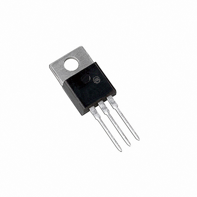
If I had wanted to spend a a few more dollars I could have purchased a "power transistor" which would give even better performance. Note that these transistors can get hot and are typically connected to a heat sink.
 |
| Power Transistor |
H-Bridge Construction
I constructed my H-Bridge on the SIK breadboard. The layout is based upon the image above. The H-Bridge is controlled by giving a control voltage to the four resistors that "control" the transistors. Using the labeling from the RobotRoom diagram, the resistors on my H-Bridge are connect to four PWM pins on the Arduino as follows:
R1 = P6
R2 = P9
R3 = P10
R4 = P11
The H-bridge is powered by an external power source - I am using a 4.8 V NiMH battery pack. There is a wire that connects the GND of the battery to the GND of the Arduino board.
With these connections made, the DC motor can be connected to the H-Bridge. The one shown in the picture below is a small geared motor that is rated for less than 6 V.
H-Bridge operation
The H-Bridge is able to control the motor by applying a combination of GND or +V to the four resistors. For the set-up shown the control requirements are summarized in the following table
|
Command
|
R1
|
R2
|
R3
|
R4
|
|
Coast/Roll/Off:
|
GND
|
+VDC
|
GND
|
+VDC
|
|
Forward:
|
GND
|
GND
|
+VDC
|
+VDC
|
|
Reverse:
|
+VDC
|
+VDC
|
GND
|
GND
|
|
Brake/Slow Down:
|
+VDC
|
+VDC
|
+VDC
|
+VDC
|
The Arduino can be used to control the motor by setting the pins 6, 9, 10, 11 to digital output and then setting them HIGH or LOW depending on whether R1, R2, R3, R4 should be either +VDC or GND. This mode of operation allows the motor direction to be controlled and to implement the "braking" option.
Another option is to use the PWM capability of the Arduino board. This mode of operation allows for control of both motor speed and direction.
The video below shows the H-Bridge controlling a motor. The code that is being used is included following the video. Note that I am just setting the motor speed to a given value. If you want to control the speed, you could set the speed value by using analogRead to read in some type of analog control signal like a potentiometer.


No comments:
Post a Comment